- Home
- :
- All Communities
- :
- Products
- :
- ArcGIS for AutoCAD
- :
- ArcGIS for AutoCAD Questions
- :
- Re: Scaling DWG file in ArcPro
- Subscribe to RSS Feed
- Mark Topic as New
- Mark Topic as Read
- Float this Topic for Current User
- Bookmark
- Subscribe
- Mute
- Printer Friendly Page
Scaling DWG file in ArcPro
- Mark as New
- Bookmark
- Subscribe
- Mute
- Subscribe to RSS Feed
- Permalink
- Report Inappropriate Content
Hi folks,
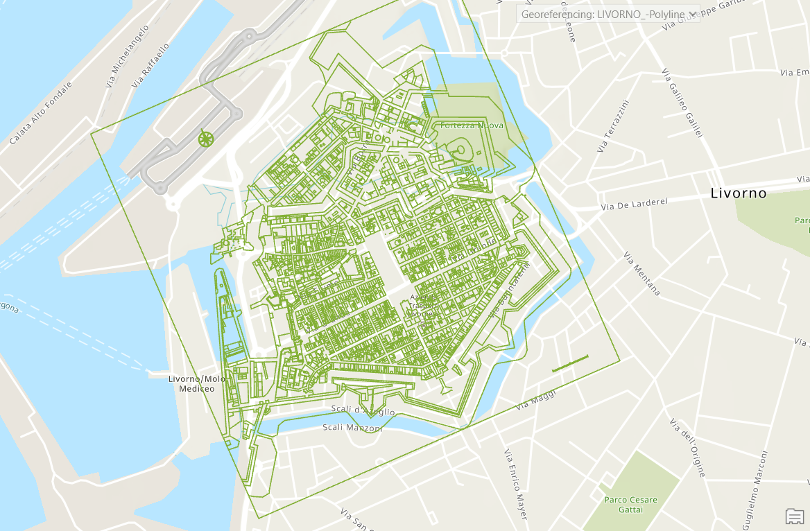
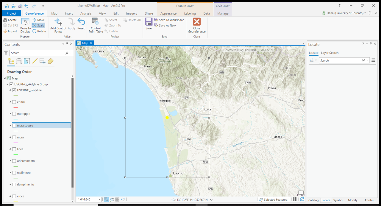
I'm trying to georeference an architectural footprint of the city of Livorno (in Italy), circa 1738, in ArcPro. The footprint was drawn up by other researchers in 2006 and is available as a DWG file (AutoCAD). I can easily add the file to a map or scene in ArcPro after defining the projection, but cannot scale it. When I go to do so, using the Georeference toolbar, the object frame to be resized is much, much bigger than the image itself (see screen shots below). The first one is the DWG file added to the map; the second is what happens when I attempt to scale it. The footprint, moss-green coloured, is visible at the bottom of that frame, right around the text for "Livorno." How can I work with this file in ArcPro so that I can scale only the map itself? I've tried clipping, but this does not work, as the DWG file contains vector data, not raster data. I've also tried converting this DWG file into a TIFF, which I can add to ArcPro, but only a few lines of it actually render. This problem happens both when I add the entire DWG file to a map, or just the polyline feature.
Thanks for your help!
- Mark as New
- Bookmark
- Subscribe
- Mute
- Subscribe to RSS Feed
- Permalink
- Report Inappropriate Content
Hi Hana,
I recommend you to use "Add Control Points" instead of scaling. Create two pairs of control points (also called links) between the CAD architectural footprint and the map will help you overlay CAD dataset perfectly on top of the basemap. It creates a .wld file in the same directory of your CAD file. Your CAD file will not be modified throughout the georeferencing process.
1. Activate "Add Control Points".
2. Select a corner on your CAD dataset (source) and then select the corresponding corner on the basemap.
3. Select the opposite corner this time and create the second link by repeating step 2
4. Click "Apply", located next to the "Add Control Points" button
5. It takes a few seconds to refresh the map. Or you can refresh the map manually
6. Save your georeferencing
By adding two pairs of control points, your cad dataset will be moved, rotated, and scaled uniformly.
Please let me know if you have any questions.
Cici
Product Engineer | CAD Team
- Mark as New
- Bookmark
- Subscribe
- Mute
- Subscribe to RSS Feed
- Permalink
- Report Inappropriate Content
We have this same issue with some of our CAD files but not others. Everything looks the same in the drawings. We are trying to figure out if there is something we can do on the CAD side to make the object frames fit the drawings without extra space, but so far haven't had any luck. If you have figured out an answer, please post it! Thanks.
- Mark as New
- Bookmark
- Subscribe
- Mute
- Subscribe to RSS Feed
- Permalink
- Report Inappropriate Content
The issue is sometimes the CAD drawings are not clean, meaning there are some redundant CAD objects, for example, a point far away from the main model that you can't see. This will bring noise when calculating the model extent.
I want to share about this free AutoCAD extension - ArcGIS For AutoCAD
It allows you to georeference and publish CAD files as GIS features directly to ArcGIS Online within the AutoCAD environment. This means you can avoid the hassle of dealing with the view frame issue in Pro. I highly recommend trying it out!