- Home
- :
- All Communities
- :
- Products
- :
- Mapping
- :
- Mapping Questions
- :
- Re: Is it possible to take pre-existing buffers, m...
- Subscribe to RSS Feed
- Mark Topic as New
- Mark Topic as Read
- Float this Topic for Current User
- Bookmark
- Subscribe
- Mute
- Printer Friendly Page
Is it possible to take pre-existing buffers, make them "flexible", and overlay those buffers onto a topo map, so that the buffer would reflect the contours?
- Mark as New
- Bookmark
- Subscribe
- Mute
- Subscribe to RSS Feed
- Permalink
- Report Inappropriate Content
Some background, so I work for and go to school at West Virginia University and I have been subcontracted to work with the DEP on stream management and analysis for the entire state. My most recent project has been to create buffers around streams leading to surface water intakes in order to help monitor chemical spills and also regulate tanks used by oil and gas companies.
My problem is that when creating the buffers around the streams I failed to include elevation and slope when calculating the distance of the buffers from the stream center (left and right banks for major rivers). My idea is to take the buffers I have (~160 of them) and make them flexible to reflect the topography because 1000 ft linearly looks a lot different than when that same 1000 ft would "decay" because of the topography and slope. I imagine my buffers being able to snap to contour lines to limit the planar length and reflect the topography.
I'm also wondering if using any tools in the 3D analyst would be of use, tools such as 3D length...I'm just not sure.
I'm aware that this could be solved by re delineating these buffers by working out of grid and also using cost-path but I would like to save myself the trouble of having to do these again since the entire project took about 6 months due to tedious calculations and attributions.
Thanks!
I am using Arc Map 10.3 and surrounding software.
- Mark as New
- Bookmark
- Subscribe
- Mute
- Subscribe to RSS Feed
- Permalink
- Report Inappropriate Content
Ouch. This sounds like a thorny policy issue. As Dan Patterson pointed out, the Buffer is an abstraction to begin with, with the general idea being that activities within its extent are a likely risk to a water feature. But in your case it could be argued in the real-world that a facility upslope of the buffer (even a 3D one) but just outside it would be a risk too, as a steep slope may make it more conducive for a spill to reach the water. And conversely a facility inside the buffer but downslope from the water feature may not be a risk to the water feature. So some potential "exceptions".
In the Environmental policy world, using a normal buffer (not 3D) is typically done as pragmatic trade-off in trying to protect a resource in a standardized way. It is a "one size fits all" approach that tries to achieve protection by balancing the cost of analysis for a multitude of varied sites with the Administrative realities of doing so, realizing that it is not perfect for each site.
For example, here in California the State mandates a specific distance buffer (2D) around Vernal Pool features, as they are considered by the State to be Sensitive Habitat and typically contain several endangered species. It is a set distance for all cases, with no variation for the topography. However, the State does provide a process where one can file for an exemption by proving that the planned activity that would fall within the buffer is actually downslope from the pool's watershed, and therefore a spill would not affect it.
So I guess it will depend on how the policymakers have developed the existing policy and how they will proceed with the new one.
Chris Donohue, GISP
- Mark as New
- Bookmark
- Subscribe
- Mute
- Subscribe to RSS Feed
- Permalink
- Report Inappropriate Content
So in essence a "flood" where at the "pour point" they want a certain horizontal offset which would diminish upstream .... (with the consequence of increasing downstream .... but we will just ignore that tidbit until someone notices it 🙂 )
- Mark as New
- Bookmark
- Subscribe
- Mute
- Subscribe to RSS Feed
- Permalink
- Report Inappropriate Content
Thank you for the response and insight, I think what might happen is that the companies filing a lawsuit (or appeal) will be able to argue their case and if they win then I will have to revise that particular zone. Which, to me doesn't make sense because that will set a precedent for these companies to file for an appeal when ever they don't want to pay out of pocket.
- Mark as New
- Bookmark
- Subscribe
- Mute
- Subscribe to RSS Feed
- Permalink
- Report Inappropriate Content
Sorry, we are wandering off topic from what you need, which is a way to do the 3D Buffer in GIS, as that may become a requirement. The backstory is always good to know.
If you haven't already checked, I'd go with Dan Patterson suggestion of checking out the code written by Xander Bakker.
This may accomplish what you need. The code was written to do a single point and buffer it in 3D. If the extent you need to buffer is not a single point, you could post the type (line, polygon) here and I suspect the many skilled Python guru's on GeoNet would likely come up with a solution.
Chris Donohue, GISP
- Mark as New
- Bookmark
- Subscribe
- Mute
- Subscribe to RSS Feed
- Permalink
- Report Inappropriate Content
So in essense they want their buffer...
Consider the following:
- proposition 1 ... a 3D buffer distance will will be used to delineate the greatest distance in the horizontal plane
- abstraction
- a buffer restriction of 100 feet exists in legislation saying nothing can be built within that buffer zone
- a cliff of 90 feet exists in the landscape within 11 feet of the river at some point along the rivers course
- conclusion
- structures can be built to the edge of the cliff and 1 foot down its surface
- proposition 2 ... a 2D buffer distance will will be used to delineate the greatest distance in the horizontal plane
- abstraction
- same buffer restriction as above
- the distance along the cliff face (ie the vertical distance) is not in the calculation of the horizontal offset
- conclusion
- structures cannot be built within the delineated 100 foot offset in the horizontal plane
- summary
- they want the cliff proposal
- everyone else wants Euclid's proposition
A bizzare, but not improbable abstraction given the wide variation in near river cliff heights and legislative offsets that exist in parts of the world.
This is not a fun situation, but when push comes to shove, Euclid always wins
- Mark as New
- Bookmark
- Subscribe
- Mute
- Subscribe to RSS Feed
- Permalink
- Report Inappropriate Content
A thing to keep in mind when doing a Cost Distance using the slope is that the system will not consider the slope in the direction of travel. It is just a value indicating the maximum slope.
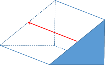
Let's say that the (maximum) slope in this case is somewhere around 45°, buy in the direction of travel (red arrow) the slope is 0°. That is why I created the script Creating a surface buffer? mentioned by Chris Donohue, GISP . It think the whole issue is not simply solvable considering just (surface) distance, but a lot more complex.
- Mark as New
- Bookmark
- Subscribe
- Mute
- Subscribe to RSS Feed
- Permalink
- Report Inappropriate Content
which is why I suggested pathdistance way back up at the top of this thread as another option to your implementation. There are some examples of the factors you can simulate
What may gained by minimizing horizontal travel in one direction will be lost if the same principles are applied in various directions of travel
- Mark as New
- Bookmark
- Subscribe
- Mute
- Subscribe to RSS Feed
- Permalink
- Report Inappropriate Content
Xander Bakker - So circling back, Cost Distance is out as a potential solution. However, the code you wrote seems like an effective solution. So one question in that regard - would it be possible to modify your code to handle inputs like lines or polygons and achieve the same result?
Shannon Shy - are your inputs that you want to buffer points, lines, or polygons (or some combination)? Also, do you have an elevations surface and access to the Spatial Analyst Extension? In short, does the code Xander Bakker wrote seem like a potential solution for your issue? If you don't know Python, no worries, people here on GeoNet can point you in the right direction.
Chris Donohue, GISP
- Mark as New
- Bookmark
- Subscribe
- Mute
- Subscribe to RSS Feed
- Permalink
- Report Inappropriate Content
Still think that the Path Distance suggested by Dan Patterson is the best option:
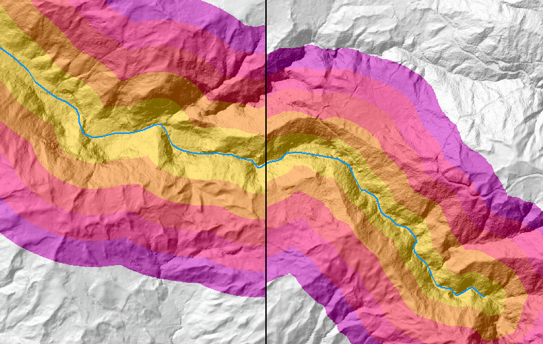
left euclidean distance and right path distance using a DEM without any cost raster
- Mark as New
- Bookmark
- Subscribe
- Mute
- Subscribe to RSS Feed
- Permalink
- Report Inappropriate Content
It may not be the solution your looking for but you could select the contours that intersect your buffers convert your buffers to lines Feature To Line—Help | ArcGIS for Desktop then merge the buffer lines and selected contours Merge—Help | ArcGIS for Desktop then convert the new feature class back to a polygon Feature To Polygon—Help | ArcGIS for Desktop then the only challenge is removing the polys that you don't need.